
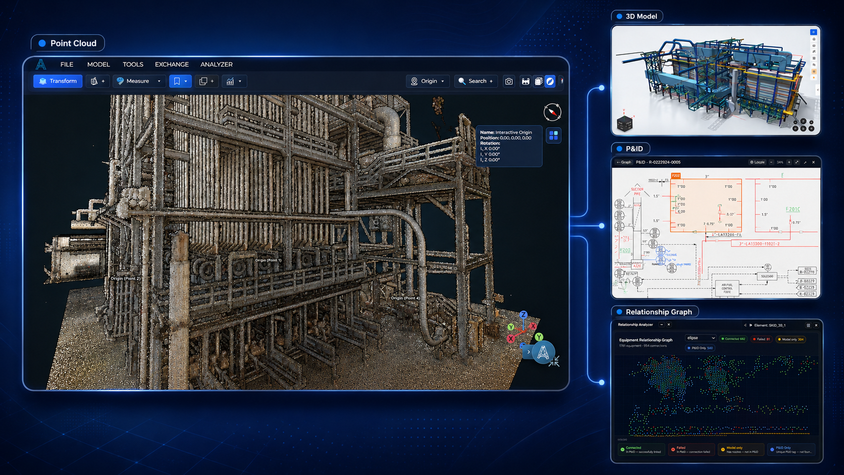
Turn industrial reality into engineering intelligence.
From scans, P&IDs, isometrics and legacy engineering documents to verified 3D models, structured data and engineering-ready decisions in one connected platform.
Reality capture
Engineering documents
ASETS
Verified digital asset
Engineering
Enriched, never rebuilt
Revit, E3D, IFC, STAAD, CAESAR II
Oil & gas, chemical, water, FMCG
Engineering starts with fragmented reality.
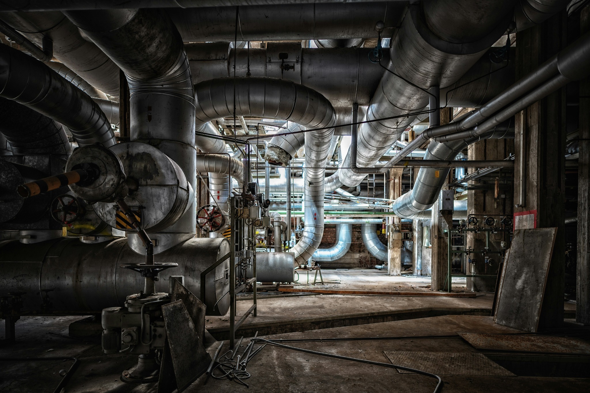
Across industrial assets, the information an engineer needs is scattered between systems that were never meant to talk to each other. Isometrics are still transcribed by hand, models are rebuilt, site conditions are rechecked, and changes are discovered too late.
TODAY
Models are rebuilt from scratch for each discipline
TODAY
Information is transcribed out of drawings by hand
TODAY
Site conditions are rechecked visit after visit
TODAY
Changes are discovered during construction

ASETS connects the pieces
From what exists to what engineers can trust.
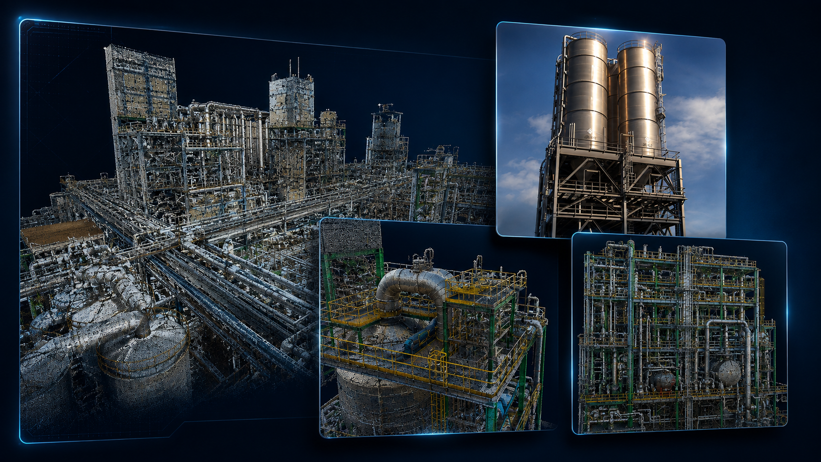
STAGE 01 / 06 - CAPTURE
Understand the physical asset
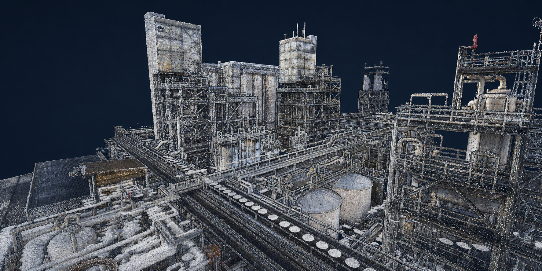
Reality capture processed into usable, visualize data - the starting truth about what is actually installed.
▹ Point clouds
▹ LiDAR
▹ Panoramic imagery
▹ 3DGS
Stage 02 / 06 - Extract
Recover the engineering information
AI reads your legacy documents and recovers the engineering data locked inside them - at 98% extraction accuracy on isometrics.
▹ P&IDs
▹ Isometrics
▹ Pipe specifications
▹ Equipment datasheets
.png)
Stage 03 / 06 - Build
Create an intelligent engineering model
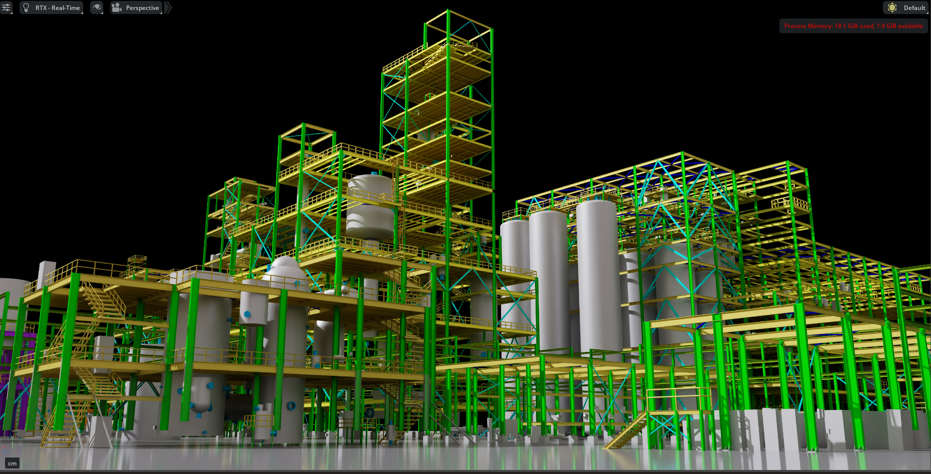
Geometry and data come together as a structured model: components recognized, tagged, and connected to their documents.
▹ Piping
▹ Equipment
▹ Structures
▹ HVAC
▹ Tags + metadata
Stage 04 / 06 - Verify
Compare engineering intent with reality
Existing CAD is checked against the scan so the gap between documented design and site condition is automatically detected.
▹ Missing
▹ Deviated
▹ Changed
▹ Unverified
Stage 05 / 06 - Engineer
Use the same model downstream
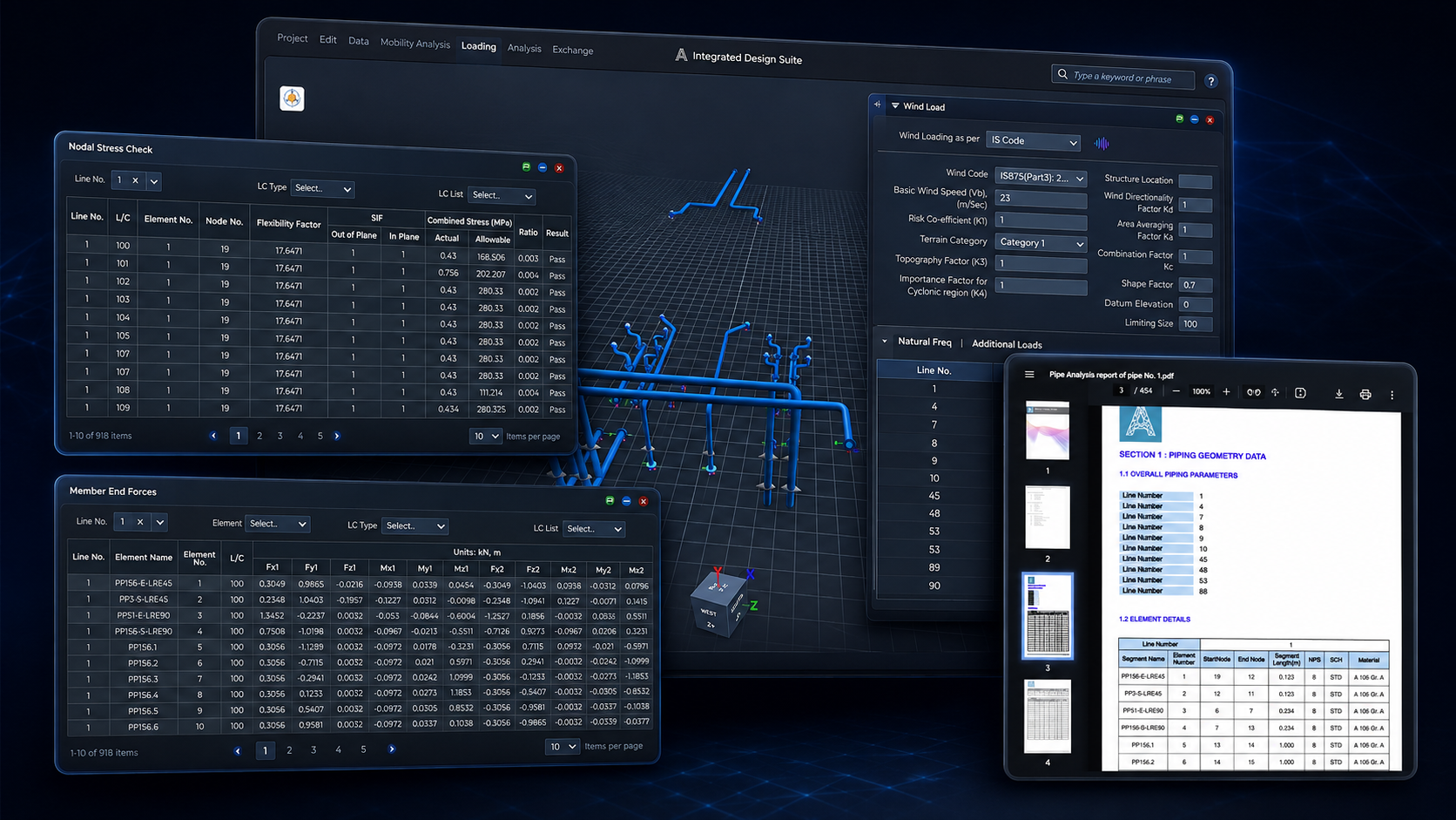
Analysis modification and planning all run on the verified model - no rebuild, no re-transcription between steps.
▹ Engineering analysis
▹ Design modifications
▹ Material takes-offs
▹ Brownfield planning
▹ FEED
Stage 06 / 06 - Deliver
Move into the tools your teams already use
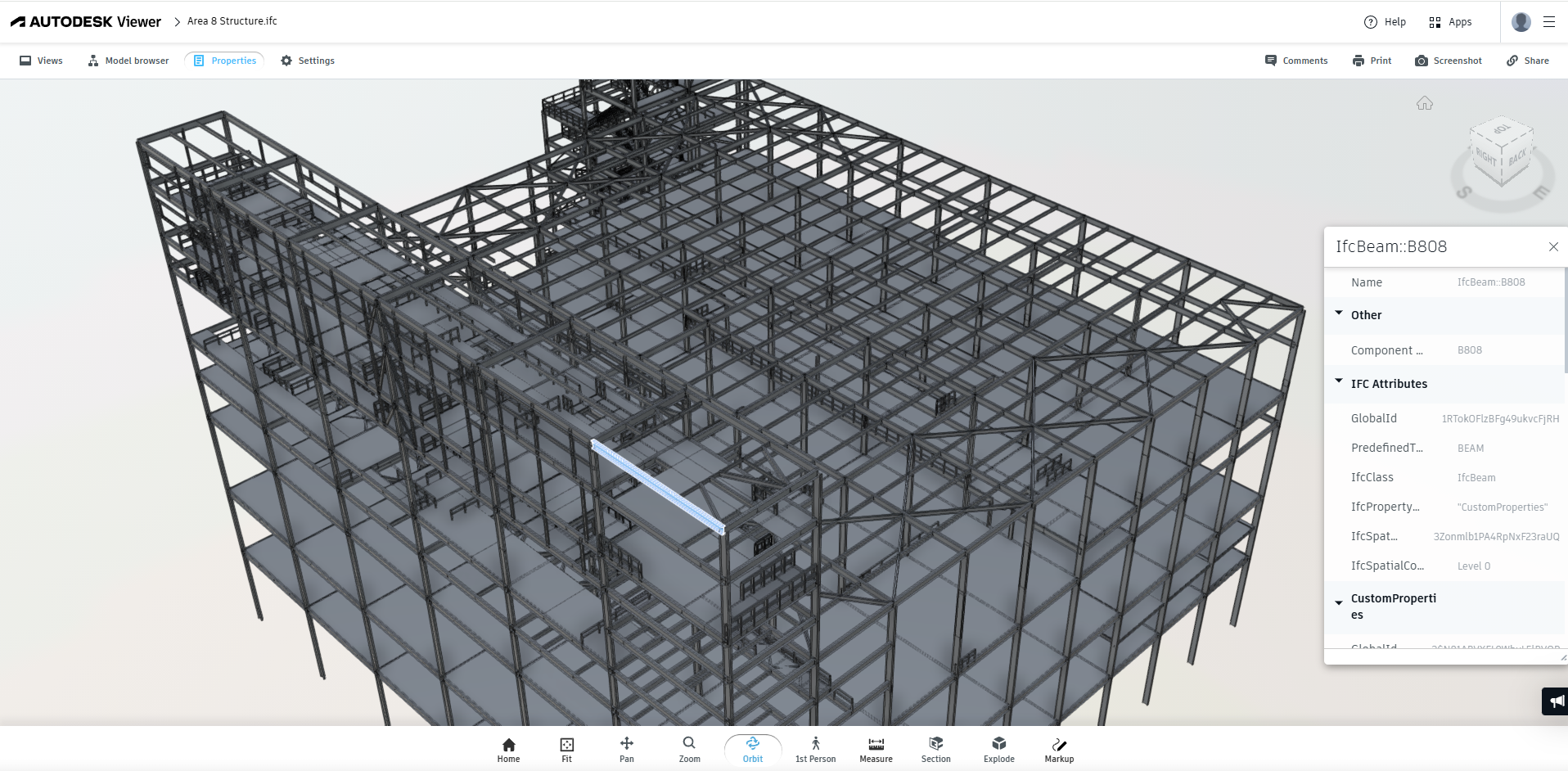
Deliverables leave in the formats your toolchain expects, so the intelligence travels with the project.
▹ Revit
▹ Navisworks
▹ E3D
▹ IFC
▹ STAAD
▹ CAESAR II
▹ FBX / OBJ / STP
One asset. One connected
engineering context.
Not scan-to-BIM. An intelligence layer around the asset, where every element carries its data and every discrepancy is visible.
Point cloud • 8.4M pts
P&ID sheets • rev C
Isometrics • PDF archive
Equipment datasheets
Legacy CAD • 2003
Equipment recognized, piping structure, tags attached, P&IDs linked, documents searchable, discrepancies highlighted.
08 Missing
Components expected in the model but not found in the scan.
03 Deviated
Installations that differs from their functional location (FLOC), or configuration.
11 Changed
Conditions that no longer align with legacy design information.
05 Unverified
Areas requiring confirmation against site conditions.
Integrated Design Solution.
Each product is an entry point to the same connected model.

IDS™ Halo
Reality capture and point-cloud processing through CAD extraction, P&ID extraction, tagging and model verification.
IDS™ Core
CAD authoring for equipment, piping, and structures, with engineering analysis and interoperability built in.

IDS™ DataOps
Extraction pipelines, a tag registry, and quality rules that keep engineering data traceable to its source.
IDS™ Viewer
Visualization, collaboration, material take-offs and model information for everyone downstream of design.
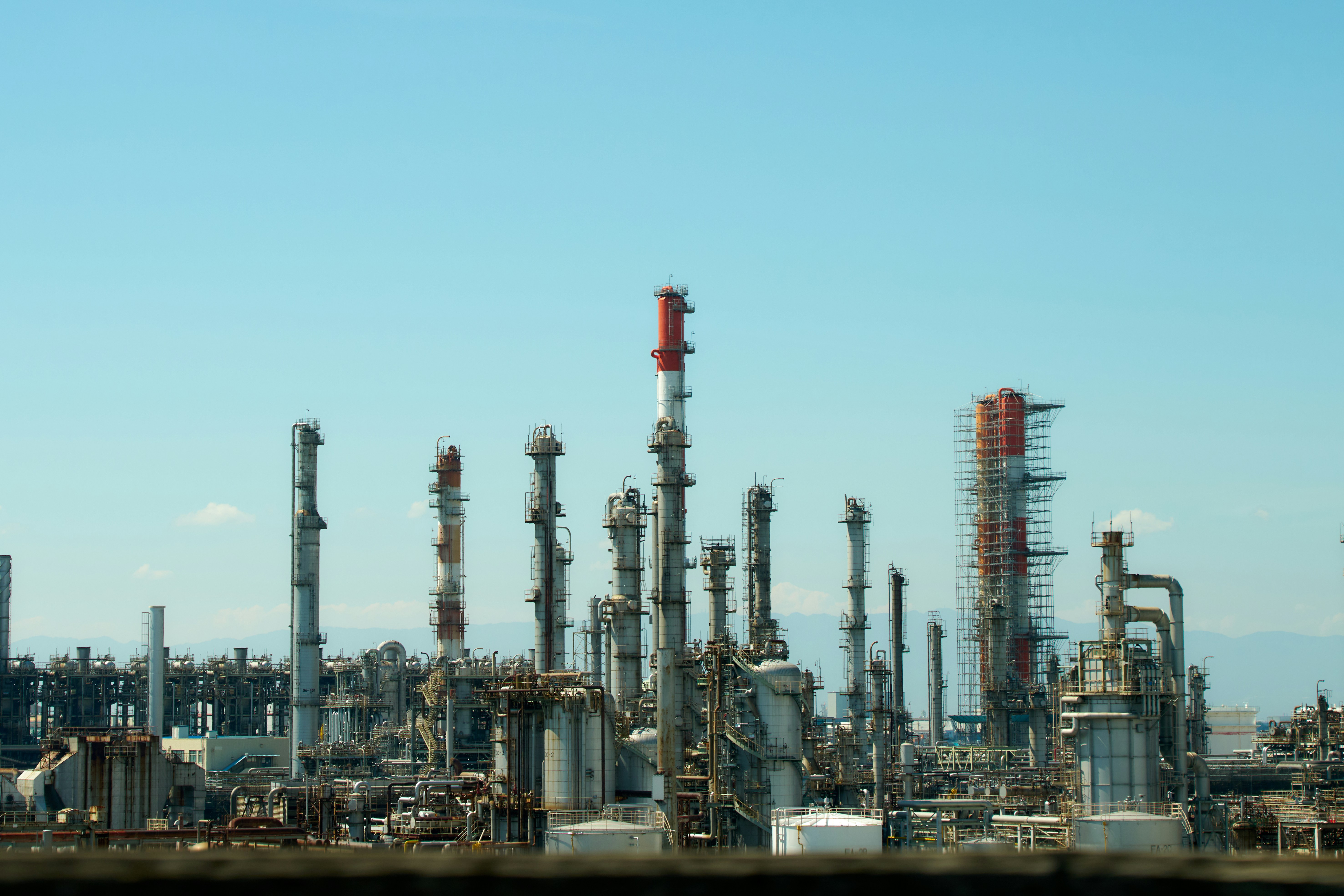
Modifying a 30-year-old facility.
You have an old P&ID, a collection of isometrics, an outdated CAD model and a new laser scan. Traditionally, engineers reconcile all four by hand.
OLD P&ID • REV 1994
ISOMETRIC ARCHIVE • PDF
OUTDATED CAD MODEL
NEW LASER SCAN
Upload documents and scan
Extract engineering data
Generate and enhance the 3D model
Compare model against the scan
Identify discrepancies
Perform the engineering modification
Export the deliverable

The model doesn't get rebuilt at every stage. It gets smarter.
Less reconstruction.
More engineering.
Measured on real brownfield and greenfield engagements, against the manual reconcile-and-remodel baseline
30 - 60 %
FASTER 3D MODEL GENERATION
98 %
ISOMETRIC EXTRACTION ACCURACY
06
STAGES. ONE CONNECTED MODEL.
09
EXPORT FORMATS OUT OF THE BOX
Less rework
Manual modelling and downstream change orders
Lower risk
Fewer on-site surprises during execution
Connected
Engineering information and 3D models in one context
Whatever you're starting with
Scan the existing asset
Visualize real site conditions
Auto-extract CAD model from scans
Validate against site conditions
Modify with confidence
Bring in engineering documents
Extract structured information
Model equipment and piping
Analyze and coordinate
Construct from trusted data

Both paths end in one engineering intelligence platform.
Stop rebuilding engineering information.
Start building on it.
From the field to the model.
From the model to engineering.
From engineering to better decisions.
30 Knowledge Park Dr, Suite 320
Fredericton, NB E3C-2R2
Canada
2, Faehrbongerten
L-5698 Welfrange
Luxembourg

© 2026 ASETS